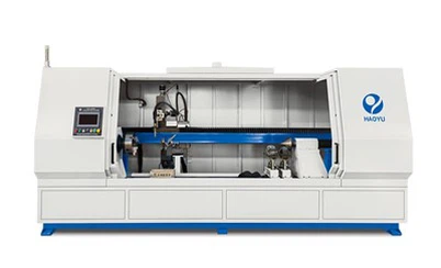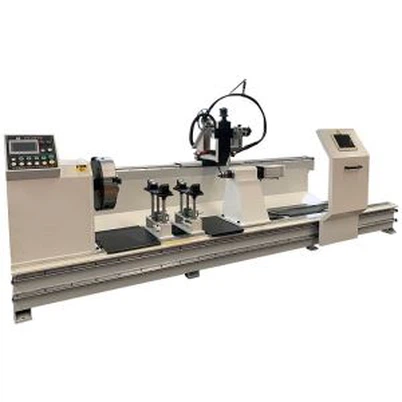


Hydraulic Cylinder Welding Machine With Hydraulic Tilting
Automate hydraulic cylinder flange fillet and bottom circumferential welds with hydraulic tilting. Send your part drawings for an application review.
Description
Hydraulic Cylinder Welding Machine Overview

Automate hydraulic cylinder flange fillet welds and cylinder bottom circumferential welds with a dedicated machine that uses hydraulic tilting to adjust the welding position of the cylinder assembly.
For cylinder manufacturers, access to the joint is an important part of planning an automatic welding operation. Different component geometries can require different welding orientations. This hydraulic cylinder welding machine combines automatic welding with hydraulic angle adjustment, helping manufacturers position the assembly to suit the joint being welded.
Automatic Welding for Two Key Cylinder Joints

Hydraulic Cylinder Flange Fillet Welding
The machine is designed for automatic welding of fillet joints on hydraulic cylinder flanges.
Flange geometry and the surrounding cylinder structure influence how the welding torch can approach the joint. The hydraulic tilting mechanism changes the orientation of the assembly, allowing the welding position to be adjusted for the flange joint layout.
When assessing an application, flange dimensions, joint location, weld size and torch clearance should be reviewed together. This helps establish whether the proposed setup can access the required weld area.
Cylinder Bottom Circumferential Welding
The machine is also intended for automatic circumferential welding at the cylinder bottom, where the cylinder tube joins the bottom component.
For this application, the equipment arrangement must suit the cylinder dimensions and the geometry of the circular joint. Hydraulic tilting provides a way to adjust the assembly's orientation as part of the welding setup.
Whether your production focuses on flange fillet welds, cylinder bottom seams or both, the application review should begin with the actual component drawing and weld requirements.
Hydraulic Tilting for Adjustable Welding Angles
The defining feature of this cylinder welding machine is its hydraulic tilting mechanism.
By changing the orientation of the cylinder assembly, the mechanism allows the joint to be presented at a suitable angle for the intended welding operation. This is particularly relevant when evaluating torch access around a flange or the joint at the cylinder bottom.
The required tilt angle depends on the workpiece and welding procedure. It should be assessed alongside the component's weight, centre of gravity, fixture arrangement and available clearance.
Hydraulic tilting supports workpiece positioning; the welding procedure, joint preparation and process settings must also be suitable for the application.
The Technical Parameters for the Hydraulic cylinder welding
| Welding position | Single-end welded flange or cylinder bottom |
| workpiece length | 500mm-2000mm |
| workpiece diameter | φ100mm-φ400mm |
| Workpiece rotation diameter | 630mm |
| Equipment load capacity | 1T |
| spindle speed | 0.01-8 r/min stepless speed regulation |
| Welding current | 60-500A, 60% duty cycle |
| Welding voltage |
16-40V |
| Manual adjustment of welding torch height |
100mm |
| Manual adjustment of welding torch left and righ | 100mm |
| Manual adjustment of welding torch forward and backward |
100mm |
| inclination |
25°~ 60° |
| Grid voltage | Three-phase 380V±15% |
The working process for the Hydraulic Cylinder Welding Machine with Hydraulic Tilting
Manual loading → workpiece clamping → pneumatic clamping of workpiece → pneumatic feeding of welding torch to welding position → CO2 gas supply → arc ignition → welding → reaching the predetermined welding angle, welding torch is raised and oscillated to weld multiple layers until welding is completed → arc termination → stopping CO2 gas supply → rapid retraction of welding torch → workpiece release → manual unloading
Please check the youtube vedio to understand the working process:
Filp automatic welding machine for hydraulic cylinder:
Tilt automatic welding machine:
A Dedicated Solution for Repetitive Cylinder Welding
For manufacturers producing recurring cylinder designs, a dedicated automatic welding machine can provide a more structured approach to repeated joint welding.
This machine is intended for production applications involving hydraulic cylinder flange fillet welds and bottom circumferential seams. Its suitability should be evaluated against your part range, production targets and quality requirements.
A useful evaluation considers the complete operation: loading the assembly, locating the joint, setting the welding angle, carrying out the weld and unloading the component. Reviewing these stages helps identify the equipment arrangement needed for your production process.
Check Compatibility with Your Cylinder Components
Before selecting a hydraulic cylinder welding machine, confirm the following application details:
- Cylinder outside diameter, overall length and assembly weight
- Flange dimensions and cylinder bottom design
- Base material and material thickness
- Joint preparation, weld location and required weld size
- Required welding position and tilt angle
- Preferred welding process and existing welding procedure
Target production volume and inspection requirements
The drawings should also show any features that could limit torch access or interfere with workpiece positioning.
Weld quality and production cycle time depend on the complete application. Representative component trials can help evaluate the proposed setup before final equipment selection.
Frequently Asked Questions
1. What is a hydraulic cylinder welding machine used for?
A hydraulic cylinder welding machine is designed to automate welding operations on cylinder components. This machine is mainly used for hydraulic cylinder flange fillet welds and cylinder bottom circumferential seams.
2. How does the hydraulic tilting mechanism help with welding?
The hydraulic tilting mechanism changes the orientation of the cylinder assembly to adjust the welding angle. This helps position the joint for torch access according to the component geometry and welding requirements.
3. Can this machine weld both cylinder flanges and cylinder bottoms?
Yes. The machine is intended for both flange fillet welding and cylinder bottom circumferential welding. Whether both joints can be welded in one setup depends on the component design, fixture arrangement and access to each weld.
4. What sizes of hydraulic cylinders can the machine accommodate?
The suitable cylinder diameter, length and weight depend on the machine specification and fixture configuration. Send drawings of your smallest and largest cylinder assemblies so the required working range can be assessed.
5. What is the adjustment range of the hydraulic tilting mechanism?
The available tilting range must be confirmed for the proposed machine configuration. Your required welding position, assembly weight and centre of gravity should be reviewed together to determine a suitable arrangement.
6. Which welding process can be used with this machine?
Welding process compatibility depends on the installed power source, welding equipment and control configuration. Specify your preferred process, base material, material thickness and weld requirements when requesting an application review.
7. Can the machine handle different cylinder models?
Suitability for multiple cylinder models depends on their dimensions, joint positions and fixture requirements. Providing drawings for your complete product range helps determine whether the models can share a setup or require fixture changes and adjustments.
8. How can I evaluate whether the machine will meet my weld quality requirements?
Evaluation should use representative components and defined acceptance criteria. Joint preparation, fit-up, material, welding parameters and workpiece positioning all affect the result. Sample welds should be inspected using the methods required by your product specification.
9. What determines the production cycle time?
Cycle time depends on weld circumference, weld size, the number of passes, welding speed and component handling. Loading, positioning, angle adjustment and unloading must also be included. A meaningful estimate should be based on your actual component and welding procedure.
10. What information should I provide to request a quotation?
Please provide component drawings, cylinder dimensions, assembly weight, material and thickness, flange and bottom joint details, required weld size, preferred welding process and target production volume. Photos or videos of your current welding operation can also help clarify access and handling requirements.
Hot Tags: hydraulic cylinder welding machine with hydraulic tilting, China, manufacturers, suppliers, factory
Send Inquiry
You Might Also Like